This page has all the information you need about configuring Powersafe Connectors in Phase 3's online store. We explain the industry jargon, power cable requirements and product information.
There are two primary types of Powersafe Connectors, Line Connectors and Panel Mount Connectors.
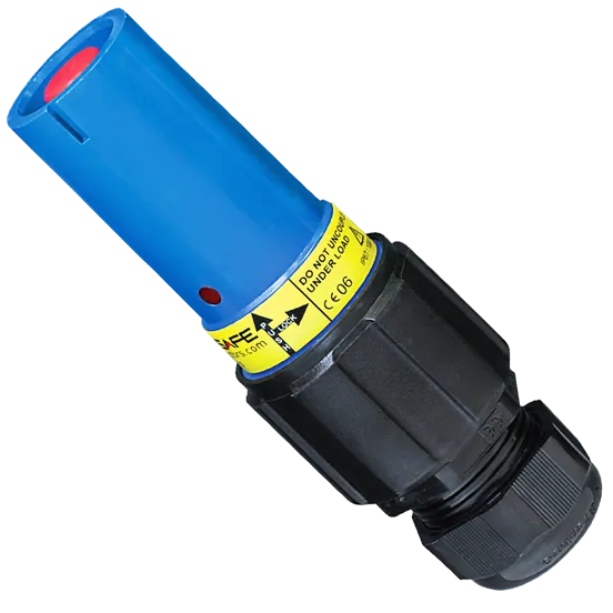
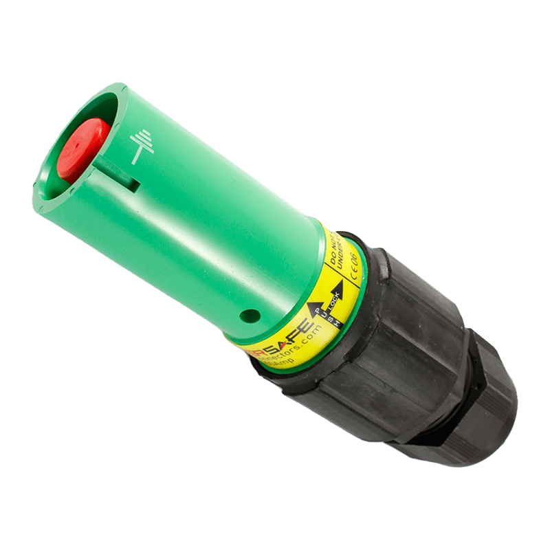
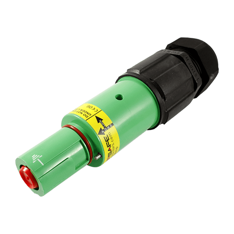
A 'Line Connector' or 'Inline' connector acts as the electrical plug for connection between an appliance and the power source. The line connector consists of an insulated casing with a single pole that fits into a Powersafe socket. The connectors are fitted with a spring-loaded plastic cap that prevents accidental finger touching of the contact. Powersafe contacts are available to suit power cable from 25mm² to 300mm².
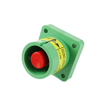
A 'Panel Mount Connector' or 'Mounted Connector' acts as the electrical socket for connection with a Powersafe Line Connector. The Panel Mount connector is mounted onto a distribution board or panel through 4 fixing holes on the flange. The Panel Mounts are terminated with M12 threaded post to a standard lug. Panel Connectors are supplied fully assembled with an M12 nut and spring washer for secure connection.
Powersafe connectors are available in Source (Male Contact / Female Insulator) & Drain (Female Contact / Male Insulator) format.
Source Connectors are usually the live end of the connection. Source connectors have a Male Contact and a Female Insulator.
Drain Connectors are usually not live ends and receive the connection. Drain Connectors have a Female Contact and a Male Insulator.
There are 2 types of termination for Powersafe, Crimp and Set Screw.
Crimp Terminations have a different sized crimp bucket on the copper contact to allow a range of cable sizes. Crimp terminations allow for an incoming cable range of 25mm² – 300mm². Phase 3’s standard size is 120mm² and 240 mm², which for instance fits with standard sized HO7RNF power cable. We recommend 3 hexagonal crimps are made with a certified crimp tool to terminate safely.
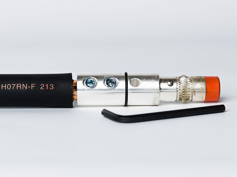
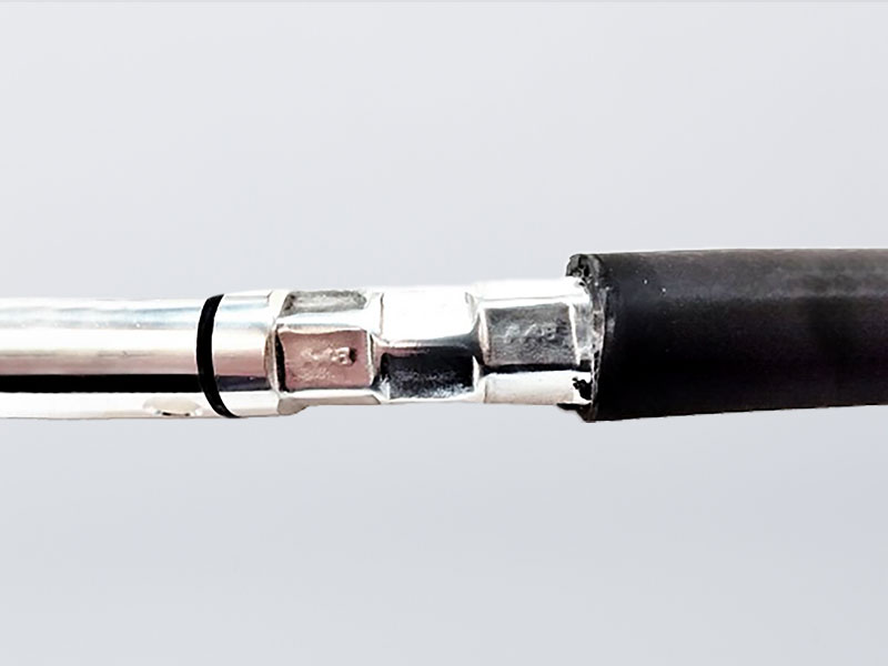
Set Screw Terminations use standard set screws to secure the connector to power cable. This type of plug are considered a temporary termination as screws can be removed with an Allen Key to remove the connector and reuse the cable. Set Screw Connectors have a standard 120mm² size and for any cable smaller (95mm² – 25mm²) a reduction kit is used to fit the contact and cable.
Set Screw Torque Minimum is 10.5 Nm
Cable Jacket Strip Length is 33mm
For more information on terminations and assembly, view our Powersafe Assembly Guide.
| Cable | Nominal Conductor OD (mm2) | Nominal Conductor OD (Inches) | Reduction Termination Sleeve Kit |
|---|---|---|---|
| #4 SC | 25 | 0.233 | R25 |
| #2 SC | 35 | 0.293 | R35 |
| #1 SC | 50 | 0.33 | R50 |
| 1/0 SC | 55 | 0.369 | R70 |
| 2/0 SC | 70 | 0.412 | R70 |
| 3/0 SC | 95 | 0.5 | R95 |
| 4/0 SC | 120 | 0.53 | N/A |
| Cable | Nominal Conductor OD (mm2) | Nominal Conductor OD (Inches) | Reduction Termination Sleeve Kit |
|---|---|---|---|
| #4 Type W | 25 | 0.233 | R25 |
| #2 Type W | 35 | 0.25 | R35 |
| #1 Type W | 50 | 0.33 | R50 |
| 1/0 Type W | 55 | 0.369 | R70 |
| 2/0 Type W | 70 | 0.412 | R70 |
| 3/0 Type W | 95 | 0.49 | R95 |
| 4/0 Type W | 120 | 0.53 | N/A |
| Cable | Nominal Conductor OD (mm2) | Nominal Conductor OD (Inches) | Reduction Termination Sleeve Kit |
|---|---|---|---|
| #4 DLO 2KV | 21.1 | 0.262 | R25 |
| #2 DLO 2KV | 33.6 | 0.315 | R35 |
| #1 DLO 2KV | 42.4 | 0.375 | R50 |
| 1/0 DLO 2KV | 53.5 | 0.435 | R70 |
| 2/0 DLO 2KV | 67.4 | 0.465 | R70 |
| 3/0 DLO 2KV | 85 | 0.535 | R95 |
| 4/0 DLO 2KV | 107 | 0.581 | N/A |
Different cable clamps are assembled onto the connector based on your cable size. The gland grips your cable to ensure an IP rating and secure connection of the connector.
We use 4 types of gland: M50, M40B, M40A and M40S (a bush is supplied for a M40SS gland).
| Cable | Nominal Jacket OD (mm2) | Cable Clamp | Reduction Cable Clamp Bushing |
|---|---|---|---|
| #4 SC | 12.07 | M40SS | PP00575 |
| #2 SC | 13.21 | M40SS3 | PP00575 |
| #1 SC | 14.61 | M40SS | PP00575 |
| 1/0 SC | 15.24 | M40S | PP00131 |
| 2/0 SC | 16.38 | M40S | PP00131 |
| 3/0 SC | 18.16 | M40S | PP00131 |
| 4/0 SC | 19.43 | M40A | N/A |
| Cable | Nominal Jacket OD (mm2) | Cable Clamp | Reduction Cable Clamp Bushing |
|---|---|---|---|
| #4 Type W | 14.86 | M40SS3 | PP00575 |
| #2 Type W | 16.51 | M40S | PP00131 |
| #1 Type W | 18.54 | M40S | PP00131 |
| 1/0 Type W | 19.05 | M40A | N/A |
| 2/0 Type W | 20.96 | M40A | N/A |
| 3/0 Type W | 23.11 | M40A | N/A |
| 4/0 Type W | 24.38 | M40A | N/A |
| 250 MCM | 25.91 | M40A | N/A |
| Cable | Nominal Jacket OD (mm2) | Cable Clamp | Reduction Cable Clamp Bushing |
|---|---|---|---|
| #4 DLO 2KV | 11.7 | M40SS | PP00575 |
| #2 DLO 2KV | 13 | M40SS | PP00575 |
| #1 DLO 2KV | 16.3 | M40S | PP00131 |
| 1/0 DLO 2KV | 17.8 | M40S | PP00131 |
| 2/0 DLO 2KV | 18.5 | M40S | PP00131 |
| 3/0 DLO 2KV | 20.3 | M40A | N/A |
| 4/0 DLO 2KV | 21.3 | M40A | N/A |
| 250 MCM | 23.9 | M40A | N/A |
| 300 MCM | 25.3 | M50 | N/A |
| 350 MCM | 26.9 | M50 | N/A |
| 400 MCM | 28.2 | M50 | N/A |
| 500 MCM | 30.5 | M50 | N/A |
After selecting your Termination, you will be asked to define your Clamping Range. The clamping Range determines the size of the gland we assemble onto the back of your connector – the size of your cable defines this. The gland grips your cable to ensure an IP rating and secure connector connection.
We use 4 types of glands: M50, M40B, M40A and M40S (a bush is supplied for an M40SS gland).
| M50 | M40B | M40A | M40S | M40SS |
|---|---|---|---|---|
| Crimp 300mm² | Crimp 300mm² | Crimp 150mm² | Set Screw 120mm² | Set Screw 70mm² |
| Crimp 240mm² | Crimp 240mm² | Crimp 120mm² | Set Screw 95mm² | Set Screw 50mm² |
| Crimp 185mm² | Crimp 185mm² | Crimp 95mm² | Set Screw 35mm² | |
| Crimp 150mm² | Crimp 70mm² | Set Screw 25mm² | ||
| Crimp 120mm² | Crimp 50mm² | |||
| Set Screw 120mm² | Crimp 35mm² | |||
| Set Screw 120mm² |
Each electrical line in a three-phase circuit has its own colour code depending on the country it is being used in. Select your line or panel mount based on your specification. Find out more about international wiring colours or ask our sales engineers if you are unsure.

Panel Mounts are secured with an M12 threaded post-termination. The standard connector is mounted to a panel through 4 fixing holes on the flange. As an alternative, flange holes can be fitted with M6 threaded inserts for either front or rear fixing. Panel connectors are supplied fully assembled and ready for direct mounting to equipment.
1. When the panel Connector is mounted in the equipment: remove the nut and washer from the threaded post section.
2. Fit your selected terminal or accessory (i.e lug) over the threaded area.
3. Refit the Washer and bolt onto the threaded area and tighten to a maximum of 12 – 14Nm.
For more information on terminations and assembly, view our Powersafe Assembly Guide.
Powersafe industrial sockets are rated either 500 amp (T5) or 800 amp (T8).
The ‘T’ stands for Threaded Post Termination. The ‘5’ and ‘8’ stand for 500A and 800A respectively.
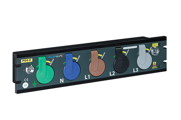
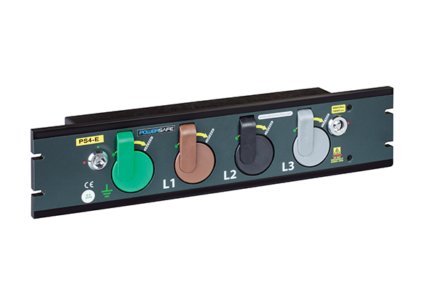
The standard Powersafe Sequential Mating Box has 5 ports for three phase electricity (Earth, Neutral, Live 1, Live 2, Live 3). However, some electrical specifications do not require a neutral line, therefore we manufacture a 4 port box. Alternatively, you can use a 5 port box with a dummy connector to transform it into a 4 port box for temporary applications – please ask our Sales Manager.
The Powersafe Box is available in both source and drain versions.
Source Boxes are usually the live end of the connection. The Source Powersafe Box accepts connection with Drain Connectors. Drain Boxes are usually not live ends and receive the connection. The Drain Powersafe Box accepts connection with Source Connectors.
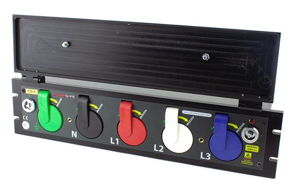
The Powersafe Power Distribution Box comes with an optional Lid as an extra. The product lid ensures an IP67 rating when not in use and protects the box from the environmental damage.
As the box is often left unused as a backup for power outages, it is recommended that the lidded version is purchased.


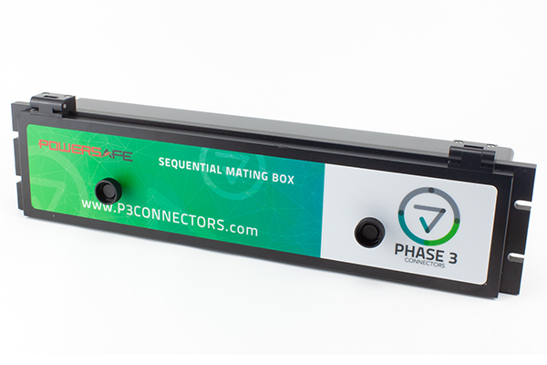
The Powersafe Sequential Mating Box has a straight front panel that comes in two panel sizes, 88mm and 108mm.
88mm (2U) box: H= 88mm, W= 483mm, D= 130mm
108mm (4U) box: H= 108mm, W= 483mm, D= 130mm
Within different racking and panel mounting applications different sizes are required.

The mark of UL approval is granted by the Underwriters Laboratories company, an independent safety science organisation dedicated to promoting a safe living and working environment. With over a century of expertise in innovating safety solutions, UL helps to safeguard people, products and places, whilst facilitating trade and providing buyers with peace of mind. You can find out more about UL certification and the tests that are carried out to gain certification, by visiting the UL website.
Phase 3’s Compliance Manager, Lee Corrigan, who led the project for UL approval said, “It’s been an enjoyable challenge gaining UL approval for myself and the team, who have worked extremely hard on this project. It’s great for the product to be recognised for its safety features and high quality. We feel this will help open many doors in the US and other markets for us as it’s now one of the highest-rated single pole connectors with UL approval.”
UL Certification is usually required in the USA and Canada.
Powersafe UL Connectors are rated slightly lower to match with UL Certified power cable current ratings – this helps users avoid confusion and adhere to UL testing standards. Our standard 500A connectors are downgraded to 455A and our standard 800A connector is downgraded to 615A.
In line with the adjusted ratings, UL Connectors are only available for devices with terminations below Crimp 150mm² and Set Screw 120mm².
